As for all my "series" - this might very well the first and last post about it, we'll see. I have a reasonable trove of solutions on my hard-drive that were either shipped, but never published, not even shipped or were, shipped, "published" but with minimal details, as a side note of bigger presentations. Wouldn't it be a shame if they spoiled?
Warning! All of what I'm going to talk about next probably is not very meaningful if you haven't been implementing parallax-corrected cubemaps before (or rather, recently), but if you did, it will (hopefully) all make sense.
This is not going to be a gentle introduction to the topic, just a dump of some notes...
Preconvoluted specular cubemaps come with all kinds of errors, but in the past decade or so we invented a better technique, where we improve the spatial locality of the cubemap by using a proxy geometry and raycasting.
 |
| From Seb. Lagarde (link above) |
The following is an attempt to solve one of the defects parallax correction introduces, by retrofitting some math I did for area lights to see if we can come up with a good solution.
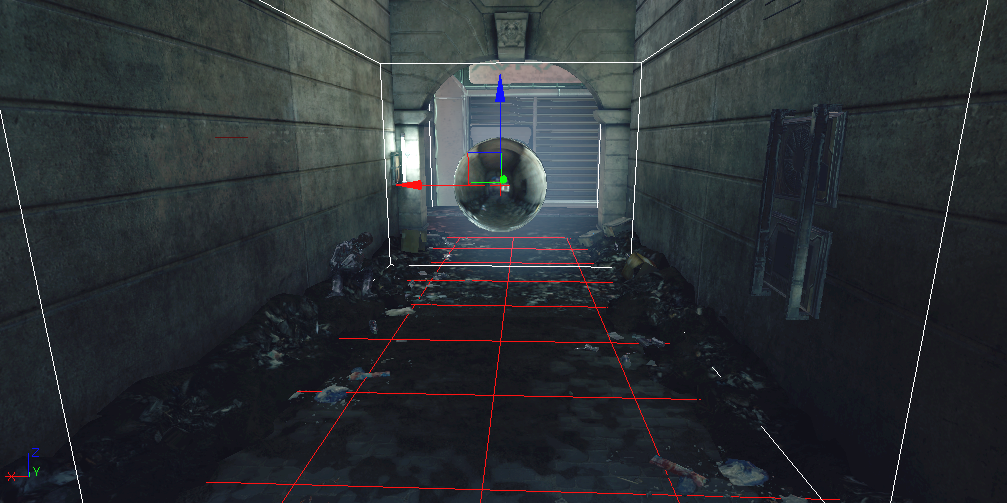
Setup is the following: We have a cubemap specular reflection probe somewhere, and we want to use that to get the specular from a location different from the cube center.
In order to do so, we trace a reflection ray from the surface to be shaded to the scene geometry, represented via some proxies that are easy to intersect, then we look the reflection baked in the probe towards the intersection point.
The problem with this setup is illustrated below. If you think of the specular lobe as projecting its intensity on the surfaces of the scene, you get a given footprint, which will be in general discontinuous (due to visibility) and stretched.
Think of our specular lobe like shining light from a torch on a surface.
Clearly, when we baked the cubemap, we were moving the torch in a given way, from the cubemap center all around. When we query though, we are looking for the lobe that a torch would create on the scene from the shaded point, towards the reflection direction (or well, technically not as a BRDF is not a lobe around the mirror reflection direction but you know that with preconvolved cubemaps we always approximate with "Phong"-like lobes).
By using the cubemap information, we get a given projected kernel which in general doesn't match -at all- the kernel that our specular lobe on the surface projects.
There is no guarantee that they are even closely related, because they can be at different distances, at different angles and "looking" at different scene surfaces (due to discontinuities).
Now, geometry is the worst offender here.
Even if the parallax proxy geometry is not the real scene, and we use proxies that are convex (boxes, k-dops...), naively intersecting planes to get a "corrected" reflection lookup clearly shows in shading at higher roughness, due to discontinuities in the derivatives.
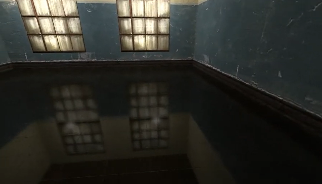 |
| From youtube - note how the reflected corners of the room appear sharp, are not correctly blurred by the rough floor material. |
The proxy geometry becomes "visible" in the reflection: as the ray changes plane, it changes the ratio of correction, and the plane discontinuity becomes obvious in the final image.
This is why in practice intersecting boxes is not great, and you'd have to find some smoother proxy geometry or "fade" out the parallax correction at high roughness. To my knowledge, everyone (??) does this "by eye", I'm not aware of a scientific approach, motivated in approximations and errors.
Honestly today I cannot recall what ended up shipping at the time, I think we initially had the idea of "fading" the parallax correction, then I added a weighting scheme to "blend" the intersection (ray parameter) between planes, and I also "pushed away" the parallax planes if we are too near them.
In theory you could intersect something like a rounded box primitive, control the rounding with the roughness parameter, and reason about Jacobians (derivatives, continuity of the resulting filtering kernel, distortion...) but that sounds expensive and harder to generalize to k-dops.
The second worst "offender" with parallax correction is the difference in shape of the specular lobes, the precomputed one versus the "ideal" one we want to reconstruct, that happens even when both are projected on the same plane (i.e. in absence of visibility discontinuities).
The simplest correction to make is in the case where the two lobes are both perpendicular to a surface, the only difference being the distance to it.
This is relatively easy as increasing the distance looks close enough to increasing the roughness. Not exactly the same, but close enough to fit a simple correction formula that tweaks the roughness we fetch from the cubemap based on the ratio between the cubemap-to-intersection distance and the surface-to-intersection one:
From this observation we know we can use numerical fitting and precomputation to find a correction factor from one model to another.
Then, we can take that fitted data and either using a lookup for the conversion or we can find an analytic function that approximates it.
This methodology is what I described at
Siggraph 2015 and have used many times since. Formulate an hypothesis: this can be approximated with that. Use brute force to optimize free parameters. Visualize the fitting and end results versus ground truth to understand if the process worked or if not, why not (where are the errors). Rinse and repeat.
Here you can see the first step. For every roughness (alpha) and distance, I fit a GGX D lobe with a new alpha', here adding a multiplicative scaling factor and an additive offset (subtractive, really, as the fitting will show).
Why we use an additive offset? Well, it helps with the fitting, and it should be clear why, if we look at the previous grid. GGX at high roughness has long tail that turns "omnidirectional", whilst a low roughness lobe that is shining far away from a plane does not exhibit that omnidirectional factor.
We cannot use it though, we employ only to help the fitting process find a good match. Why? Well, first, because we can't express it with a single fetch in a preconvolved cubemap mip hierarchy (we can only change the preconvolved lobe by a multiplicative factor), but also note that it is non-zero only in the area where the roughness maxes out (we cannot get rougher than alpha=1), and in that area there is nothing really that we can do.
Of course, next we'd want to find an analytic approximation, but also make sure everything is done in whatever exact association there is from cubemap mip level to alpha, ending up with a function that goes from GGX mip selection to adjusted GGX mip selection (given the distance).
This is really engine-dependent, and left as an exercise to the reader (in all honesty, I don't even have the final formulas/code anymore)
Next up is to consider the case where the cubemap and the surface are not perpendicular to the intersection plane (even keeping that to be just a plane, so again, no discontinuities). Can we account for that as well?
To illustrate the problem, the following shows the absolute value of the cosine of the angle of the intersection between the reflection direction and the proxy planes in a scene.
This is much harder to fit a correction factor for. The problem is that the two different directions (the precomputed one and the actual one) can be quite different.
Same distance, one kernel hits at polar angle Pi/3,0, the second -Pi/3,Pi/3. How do you adjust the mip (roughness) to make one match the other?
One possible idea is to consider how different is the intersection at an angle and the corresponding perpendicular one.
If we have a function that goes from angle,distance -> an isotropic, perpendicular kernel (roughness', angle=0, same distance) then we could maybe go from the real footprint we need for specular to an isotropic footprint, and from the real footprints that we have in the cubemap mips to the isotropic and search for the closest match between the two isotropic projections.
The problem here is that really, with a single fetch/isotropic kernel, it doesn't seem that there a lot to gain by changing the roughness as function of the angle.
In the following, I grapth projections at an angle compared to perpendicular lobe (GGX D term only).
All graphs are with alpha = 0.1, distance = plane size (so it's equivalent to the kernel at the center of a prefiltered cubemap when you ignore the slant).
Pi/6 - the two lobes seem "visually" very close:
At Pi/2.5 we get a very long "tail" but note that the width of the central part of the kernel seems still to fit the isotropic fetch without any change of roughness.
Now here "seems to fit" really doesn't mean much. What we should do is to look at rendered results, compare to ground truth / best effort (i.e. using sampling instead of prefiltering, whilst still using the assumption of representing radiance with the baked, localized cubemap), and if we want to then use numerical methods, do so with an error measure based on some perceptual metric.
And this is what I did, but failed to find any reasonable correction, keeping the limitation of a single fetch. The only hope is to turn to multiple fetches, and optimize the preconvolution specifically to bake data that is useful for the reconstruction, not using a GGX prefiltering necessarily.
I suspect that actually the long anisotropic tail created by the BRDF specular lobe is not, visually, an huge issue.
The problem that what we get is (also) the opposite, from the point of view of the reconstruction, we get tails "baked" into the prefiltered cube at arbitrary angles (compared to the angles we need for specular on surfaces), and these long tails create artifacts.
To account for that, the prefiltering step should probably take directly into account the proxy geometry shape. I.e. if these observations are correct, they point towards the idea that parallax-corrected cubemaps should be filtered by a fixed distance (relative to projected texel size), perpendicular to the proxy plane kernel.
That way when we query the cubemap we have only to convert the projected specular kernel to a kernel perpendicular to the surface (which would be ~ the same kernel we get at that roughness and same distance, just perpendicular), and then look in the mip chain the roughness that gives us a similar prefiltered image, by doing a distance-ratio-to-roughness adjustment as described in the first part of this text.