Search this blog

Showing posts with label Rendering ideas. Show all posts

15 March, 2023

Half baked: Dynamic Occlusion Culling

The following doesn't work (yet), but I wanted to write something down both to put it to rest for now, as I prepare for GDC, and perhaps to show the application of some of the ideas I recently wrote about here.

A bit of context. Occlusion culling (visibility determination) per se is far from a solved problem in any setting, but for us (Roblox) it poses a few extra complications:

  1. We don't allow authoring of "technical details" - so no artist-crafted occluders, cells and portals, and the like.
  2. Everything might move - even if we can reasonably guess what is dynamic in a scene, anything can be changed by a LuaU script.
  3. We scale down to very low-power and older devices - albeit this might not necessarily be a hard constraint here, as we could always limit the draw distance on low-end to such degrees that occlusion culling would become less relevant. But it's not ideal, of course.

That said, let's start and find some ideas on how we could solve this problem, by trying to imagine our design landscape and its possible branches. 
Image from https://losslandscape.com/gallery/

Real-time "vs" Incremental

I'd say we have a first obvious choice, given the dynamic nature of the world. Either we try to do most of the work in real-time, or we try to incrementally compute and cache some auxiliary data structures, and we'd have then to be prepared to invalidate them when things move.

For the real-time side of things everything (that I can think of) revolves around some form of testing the depth buffer, and the decisions lie in where and when to generate it, and when and where to test it. 

Depth could be generated on the GPU and read-back, typically a frame or more late, to be tested on CPU, it could be generated and tested on GPU, if our bottlenecks are not in the command buffer generation (either because we're that fast, or because we're doing GPU-driven rendering), or it could be both generated and tested on CPU, via a software raster. Delving deeper into the details reveals even more choices. 

On GPU you could use occlusion queries, predicated rendering, or a "software" implementation (shader) of the same concepts, on CPU you would need to have a heuristic to select a small set of triangles as occluders, make sure the occluders themselves are not occluded by "better" ones and so on.

All of the above, found use in games, so on one hand they are techniques that we know could work, and we could guess the performance implications, upsides, and downsides, and at the same time there is a lot that can still be improved compared to the state of the art... but, improvements at this point probably lie in relatively low-level implementation ideas. 

E.g. trying to implement a raster that works "conservatively" in the sense of occlusion culling is still hard (no, it's not the same as conservative triangle rasterization), or trying to write a parallelized raster that still allows doing occlusion tests while updating it, to be able to occlude-the-occluders while rendering them, in the same frame, things of that nature. 

As I wanted to explore more things that might reveal "bigger" surprises, I "shelved" this branch...

Let's then switch to thinking about incremental computation and caching.

Caching results or caching data to generate them?

The first thing that comes to mind, honestly, is just to cache the results of our visibility queries. If we had a way to test the visibility of an object, even after the fact, then we could use that to incrementally build a PVS. Divide the world into cells of some sort, maybe divide the cells per viewing direction, and start accumulating the list of invisible objects.

All of this sounds great, and I think the biggest obstacle would be to know when the results are valid. Even offline, computing a PVS from raster visibility is not easy, you are sampling the space (camera positions, angles) and the raster results are not exact themselves, so, you can't know that your data structure is absolutely right, you just trust that you sampled enough that no object was skipped. For an incremental data structure, we'd need to have a notion of "probability" of it being valid.

You can see a pattern here by now, a way of "dividing and conquering" the idea landscape, the more you think about it, the more you find branches and decide which ones to follow, which ones to prune, and which ones to shelve. 

Pruning happens either because a branch seems too unlikely to work out, or because it seems obvious enough (perhaps it's already well known or we can guess with low risk) that it does not need to be investigated more deeply (prototyping and so on). 

Shelving happens when we think something needs more attention, but we might want to context-switch for a bit to check other areas before sorting out the order of exploration...

So, going a bit further here, I imagined that visibility could be the property of an object - a visibility function over all directions, for each direction the maximum distance at which it would be unoccluded - or the property of the world, i.e. from a given region, what can that region see. The object perspective, even if intriguing, seems a mismatch both in terms of storage and in terms of computation, as it thinks of visibility as a function - which it is, but one that is full of discontinuities that are just hard to encode.

If we think about world, then we can imagine either associating a "validity" score to the PVS cells, associating a probability to the list of visible objects (instead of being binary), or trying to dynamically create cells. We know we could query, after rendering, for a given camera the list of visible objects, so, for an infinitesimal point in 5d space, we can create a perfect PVS. From there we could cast the problem as how to "enlarge" our PVS cells, from infinitesimal points to regions in space. 

This to me, seems like a viable idea or at least, one worth exploring in actual algorithms and prototypes. Perhaps there is even some literature about things of this nature I am not aware of. Would be worth some research, so for now, let's shelve it and look elsewhere!

Occluders

Caching results can be also thought of as caching visibility, so the immediate reaction would be to think in terms of occluder generation as the other side of the branch... but it's not necessarily true. In general, in a visibility data structure, we can encode the occluded space, or the opposite, the open space. 

We know of a popular technique for the latter, portals, and we can imagine these could be generated with minimal user intervention, as Umbra 3 introduced many years ago the idea of deriving them through scene voxelization.

Introduction to Occlusion Culling | by Umbra 3D | Medium

It's realistic to imagine that the process could be made incremental, realistic enough that we will shelve this idea as well...

Thinking about occluders seem also a bit more natural for an incremental algorithm, not a big difference, but if we think of portals, they make sense when most of the scene is occluded (e.g. indoors), as we are starting with no information, we are in the opposite situation, where at first the entire scene is disoccluded, and progressively might start discovering occlusion, but hardly "in the amount" that would make most natural sense to encode with something like portals. There might be other options there, it's definitely not a dead branch, but it feels unlikely enough that we might want to prune it.

Here, is where I started going from "pen and paper" reasoning to some prototypes. I still think the PVS idea that we "shelved" might get here as well, but I chose to get to the next level on occluder generation for now. 

From here on the process is still the same, but of course writing code takes more time than rambling about ideas, so we will stay a bit longer on one path before considering switching. 

When prototyping I want to think of what the real risks and open questions are, and from there find the shortest path to an answer, hopefully via a proxy. I don't need at all to write code that implements the way I think the idea will work out if I don't need to - a prototype is not a bad/slow/ugly version of the final product, it can be an entirely different thing from which we can nonetheless answer the questions we have.

With this in mind, let's proceed. What are occluders? A simplified version of the scene, that guarantees (or at least tries) to be "inside" the real geometry, i.e. to never occlude surfaces that the real scene would not have occluded. 

Obviously, we need a simplified representation, because otherwise solving visibility would be identical to rendering, minus shading, in other words, way too expensive. Also obvious that the guarantee we seek cannot hold in general in a view-independent way, i.e. there's no way to compute a set of simplified occluders for a polygon soup from any point of view, because polygon soups do not have well-defined inside/outside regions.

So, we need to simplify the scene, and either accept some errors or accept that the simplification is view-dependent.  How? Let's talk about spaces and data structures. As we are working on geometry, the first instinct would be to somehow do computation on the meshes themselves, in object and world space. 

It is also something that I would try to avoid, pruning that entire branch of reasoning, because geometric algorithms are among the hardest things known to mankind, and I personally try to avoid writing them as much as I can. I also don't have much hope for them to be able to scale as the scene complexity increases, to be robust, and so on (albeit I have to say, wizards at Roblox working on our real-time CSG systems have cracked many of these problems, but I'm not them).

World-space versus screen-space makes sense to consider. For data structures, I can imagine point clouds and voxels of some sort to be attractive.

First prototype: Screen-space depth reprojection

Took a looong and winding road to get here, but this is one of the most obvious ideas as CryEngine 3 showed it to be working more than ten years ago. 

Secrets of CryEngine 3

I don't want to miscredit this, but I think it was Anton Kaplanyan's work (if I'm wrong let me know and I'll edit), and back then it was dubbed "coverage buffer", albeit I'd discourage the use of the word as it already had a different meaning (the c-buffer is a simpler version of the span-buffer, a way to accelerate software rasterization by avoiding to store a depth value per pixel). 

They simply took the scene depth after rendering, downsampled it, and reprojected - by point splatting - from the viewpoint of the next frame's camera. This creates holes, due to disocclusion, due to lack of information at the edges of the frame, and due to gaps between points. CryEngine solved the latter by running a dilation filter, able to eliminate pixel-sized holes, while just accepting that many draws will be false positive due to the other holes - thus not having the best possible performance, but still rendering a correct frame. 
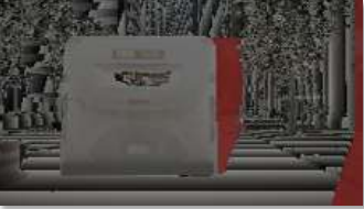
Holes, in red, due to disocclusions and frame edges.

This is squarely in the realm of real-time solutions though, what are we thinking? 

Well, I was wondering if this general idea of having occluders from a camera depthbuffer could be generalized a bit more. First, we could think of generating actual meshes - world-space occluders, from depth-buffer information. 

As we said above, these would not be valid from all view directions, but we could associate the generated occluders from a set of views where we think they should hold up.

Second, we could keep things as point clouds and use point splatting, but construct a database from multiple viewpoints so we have more data to render occluder and fill the holes that any single viewpoint would create.

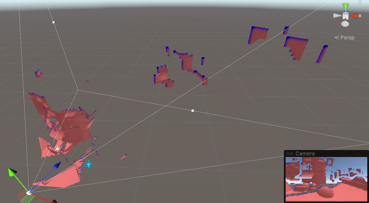
For prototyping, I decided to use Unity, I typically like to mix things up when I write throwaway code, and I know Unity enough that I could see a path to implement things there. I started by capturing the camera depth buffer, downsampling, and producing a screen-aligned quad-mesh I could displace, effectively like a heightfield. This allowed me to write everything via simple shaders, which is handy due to Unity's hot reloading.
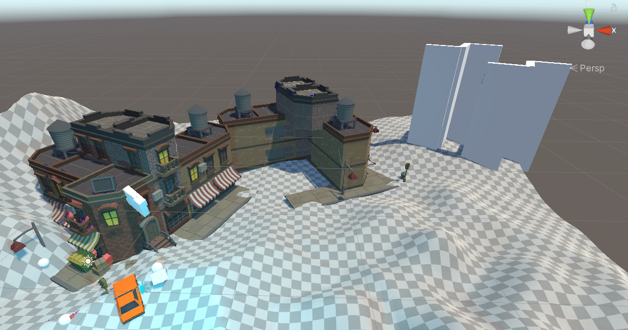
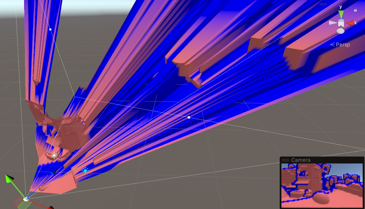
Test scene, and a naive "shrink-wrap" mesh generated from a given viewpoint

Clearly, this results in a "shrink-wrap" effect, and the generated mesh will be a terrible occluder from novel viewpoints, so we will want to cut it around discontinuities instead. In the beginning, I thought about doing this by detecting, as I'm downsampling the depth buffer, which tiles can be well approximated by a plane, and which contain "complex" areas that would require multiple planes. 

This is a similar reasoning to how hardware depth-buffer compression typically works, but in the end, proved to be silly.

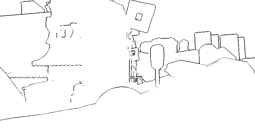
An easier idea is to do an edge-detection pass in screen-space, and then simply observe which tiles contain edges and which do not. For edge detection, I first generated normals from depth (and here I took a digression trying and failing to improve on the state of the art), then did two tests.
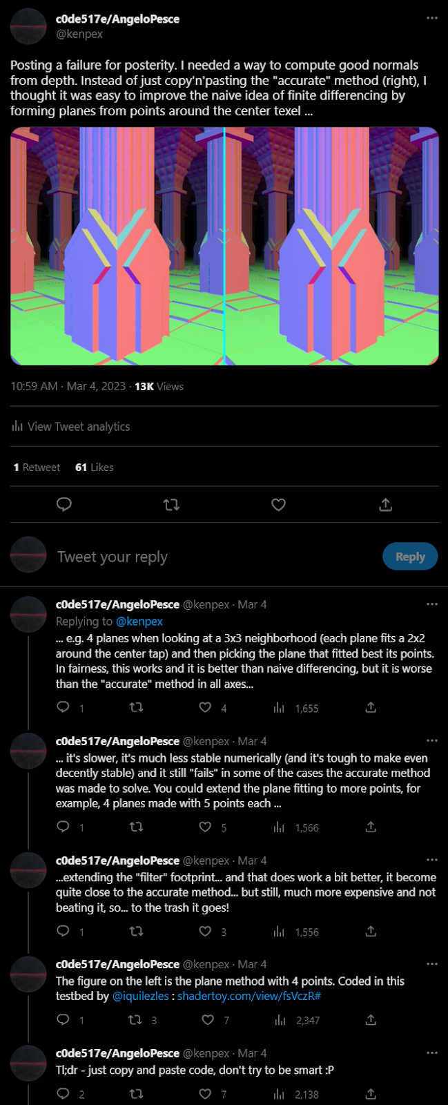
A digression...

First, if neighboring pixels are close in 3d space, we consider them connected and do not generate an edge. If they are not close, we do a second test by forming a plane with the center pixel and its normal and looking at the point-to-plane distance. This avoids creating edges connected geometry that just happens to be at a glancing angle (high slope) in the current camera view.

Depth, estimated normals, estimated edge discontinuties.

As I'm working with simple shaders, I employ a simple trick. Each vertex of each quad in my mesh has two UVs, one corresponding to the vertex location - which would sample across texels in the heightmap, and one corresponding to the center of the quad, which would sample a single texel in the heightmap. 
In the vertex shader, if a vertex is hitting an "edge" texel when sampling the first UV set, it checks the quad center UV sample as well. If this is still on an edge texel, then the whole quad is part of an edge, and I send the vertex to NaN to kill the triangles. Otherwise, I just use the height from the second sample.

In practice this is overly conservative as it generates large holes, we could instead push the "edge" quads to the farthest depth in the tile, which would hold for many viewpoints, or do something much more sophisticated to actually cut the mesh precisely, instead of relying on just quads. The farthest depth idea is also somewhat related to how small holes are filled in Crytek's algorithm if one squints enough...
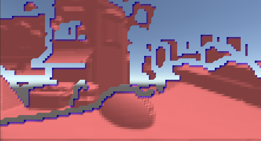
What seems interesting, anyhow, is that even with this rudimentary system we can find good, large occluders - and the storage space needed is minimal, we could easily hold hundreds of these small heightfields in memory...
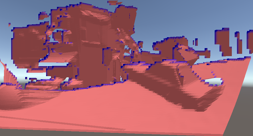
Combining multiple (three) viewpoints

So right now what I think would be possible is:

  • Keep the last depth and reproject plus close small holes from that, ala Crytek.
  • Then try to fill the remaining holes by using data from other viewpoints. 
  • For each view we can have a bounding hierarchy by just creating min-max depth mips (a pyramid), so we can test the volumes against the current reprojection buffer. And we need only to "stencil" test, to see how much of a hole we could cover and with what point density.
  • Rinse and repeat until happy...
  • Test visibility the usual way (mip pyramid, software raster of bounding volumes...)
  • Lastly, if the current viewpoint was novel enough (position and look-at direction) compared to the ones already in the database, consider adding its downsampled depth to the persistent database.

As all viewpoints are approximate, it's important not to try to merge them with a conventional depthbuffer approach, but to prioritize first the "best" viewpoint (the previous frame's one), and then use the other stored views only to fill holes, prioritizing views closer to the current camera.

If objects move (that we did not exclude from occluder generation), we can intersect their bounding box with the various camera frustums, and either completely evict these points of view from the database, or go down the bounding hierarchy / min-max pyramid and invalidate only certain texels - so dynamic geometry could also be handled.

The idea of generating actual geometry from depth probably also has some merit, especially for regions with simple occlusion like buildings and so on. The naive quad mesh I'm using for visualization could be simplified after displacement to reduce the number of triangles, and the cuts along the edges could be done precisely, instead of on the tiles. 

But it doesn't seem worth the time mostly because we would still have very partial occluders with big "holes" along the cuts, and merging real geometry from multiple points of view seems complex - at that point, we'd rather work in world-space, which brings to...

Second prototype: Voxels

Why all the complications about viewpoints and databases, if in the end, we are working with point sets? Could we store these directly in world-space instead? Maybe in a voxel grid?

Of course, we can! In fact, we could even just voxelize the scene in a separate process, incrementally, generating point clouds, signed distance fields, implicit surfaces, and so on... That's all interesting, but for this particular case, as we're working incrementally anyways, using the depth buffer is a particularly good idea. 

Going from depth to voxels is trivial, and we are not even limited to using the main camera depth, we could generate an ad-hoc projection from any view, using a subset of the scene objects, and just keep accumulating points / marking voxels.

Incidentally, working on this made me notice an equivalence that I didn't think of before. Storing a binary voxelization is the same as storing a point cloud if we assume (reasonably) that the point coordinates are integers. A point at a given integer x,y,z is equivalent to marking the voxel at x,y,z as occupied, but more interestingly, when you store points you probably want to compress them, and the obvious way to compress would be to cluster them in grid cells, and store grid-local coordinates at a reduced precision. This is exactly equivalent then again to storing binary voxels in a sparse representation. 


It is obvious, but it was important to notice for me because for a while I was thinking of how to store things "smartly", maybe allow for a fixed number of points/surfels/planes per grid and find ways to merge when adding new ones, all possible and fun to think about, but binary is so much easier. 

In my compute shader, I am a rebel bit-pack without even InterlockedOR because I always wanted to write code with data races that still converge to the correct result! 
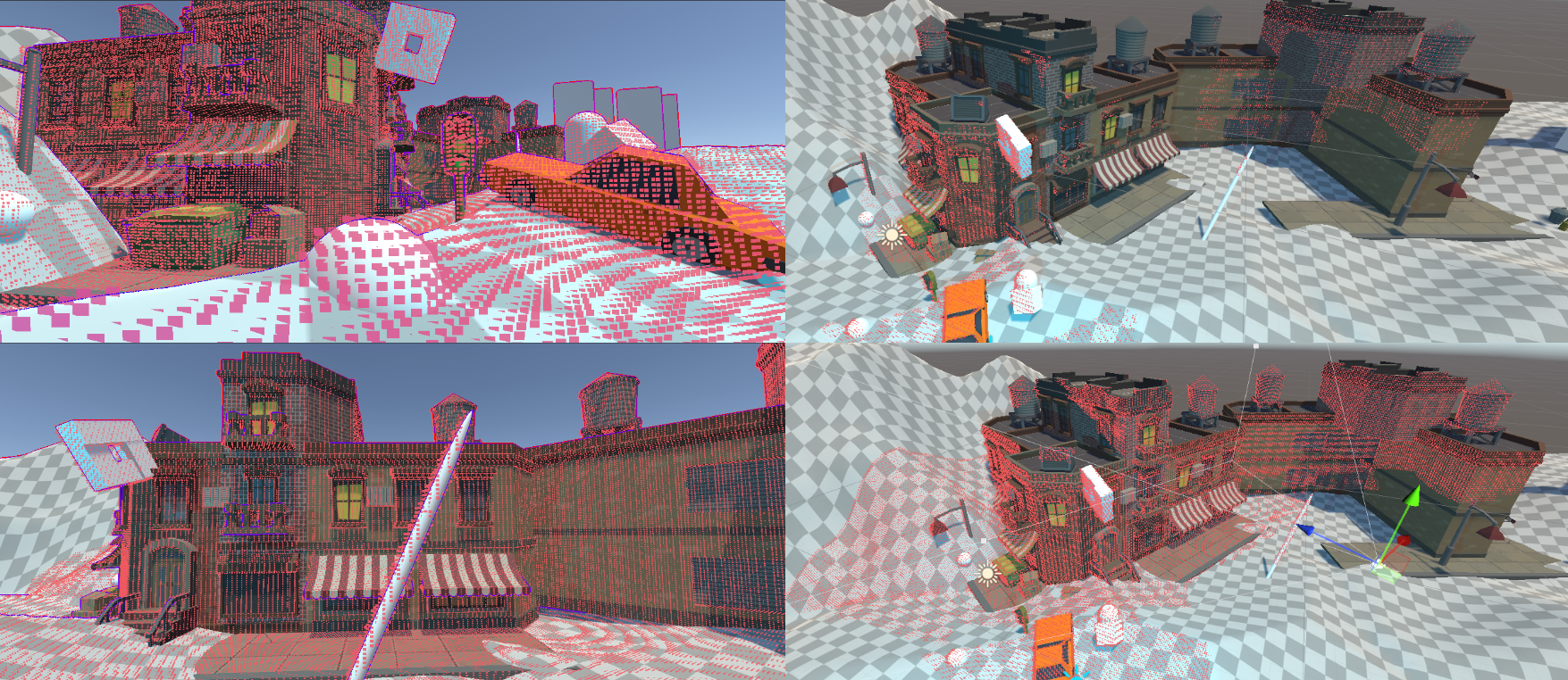
As the camera moves (left) the scene voxelization is updated (left)

If needed, one could then take the binary voxel data and compute from it a coarser representation that encodes planes or SDFs, etc! This made me happy enough that even if it would be cute to figure out other representations, they all went into a shelve-mode. 

I spent some time thinking about how to efficiently write a sparse binary voxel, or how to render from it in parallel (load balancing the parallel work), how to render front-to-back if needed, all interesting problems but in practice, not worth yet solving. Shelve!

The main problem with a world-space representation is that the error in screenspace is not bounded, obviously. If we get near the points, we see through them, and they will be arbitrarily spaced apart. We can easily use fewer points farther from the camera, but we have a fixed maximum density.

The solution? Will need another blog post, because this is getting long... and here is where I'm at right now anyways!

I see a few options I want to spend more time on:

1) Draw points as "quads" or ellipsoids etc. This can be done efficiently in parallel for arbitrary sizes, it's similar to tile-based GPU particle rendering.


We could even be clever, under the assumption that splats do not overlap much: we can send them to different tiles based on their size - forming a mipmap hierarchy of buckets. In that case, we know that for each bucket there is only a small fixed number of splats that could land. Then, walking per each pixel the hierarchy from the biggest splats/fewer tiles to the smallest, you even get approximate depth sorting!

2) We could do something more elaborate to reconstruct a surface in screen-space / fill holes.

Imperfect Shadow Maps used a push-pull pyramid to fill arbitrary-sized holes for example. In our case though we would need to be more careful to only join points that are supposed to be on the same surface, and not holes that were actually present in the scene... 

A related problem would be on how to perform visibility on the point cloud itself, as clearly points father aways will poke in between closest points. That could be addressed with some kind of depth layers or a similar heuristic, allowing a near point to "occlude" a large number of background points, farther than a few voxels from it... 
These ideas have some research in the point cloud literature, but none is tailored to occlusion, which has different requirements.

3) We could reconstruct a surface for near voxels, either by producing an actual mesh (which we could cache, and optimize) or by raymarching (gives the advantage of being able to stop at first intersection). 

We'd still points at a distance, when we know they would be dense enough for simple dilation filters to work, and switch to the more expensive representation only for voxels that are too close to the camera to be treated as points.  

Inspired by MagicaVoxel's binary MC (see here a shadertoy version) - made a hack that could be called "binary sufrace nets". Note that this is at half the resolution of the previous voxel/point clouds images, and still holds up decently.

4) We could hybridize with the previous idea, and use the depth from the last frame as an initial reprojection, while then fetching from the point cloud/voxel representation for hole-filling (we'd still need some way of dealing with variable point density, but it might matter less if it's only for a few holes).

I think this is the most promising direction, it makes caching trivial, while side-stepping the biggest issues with world-space occluders, which is the fact that even a tiny error (say, 1 centimeter) if seen up close enough (in front of your virtual nose) would cause huge mis-occlusions. 

If we used the previous screenspace Z as an initial occlusion buffer, and then augment that with the world-space point cloud, we could render the latter with a near plane that is pushed far enough for the approximation error not to be problematic, while still filling the holes that the reprojection would have. Yes, the holes will still miss some occluders, as now we're not using the cache until a given distance, and worst case we could peek behind a wall causing lots of objects to be rendered... but realtime rendering is the art of finding the best compromises...

08 December, 2018

11 September, 2016

Tone mapping & local adaption

My friend Bart recently wrote a series of great articles on tone mapping, showing how localized models can be useful in certain scenarios, and I strongly advise to head over to his blog to read that one first, which motivated me to finally dump some of my notes and small experiments on the blog...

Local tone mapping refers to the idea of varying the tone mapping per pixel, instead of applying a single curve globally on the frame. Typically the curve is adapted by using some neighborhood-based filter to derive a localized adaption factor, which can help preserve details in both bright and dark areas of the image.

At the extreme, local operators give the typical "photographic HDR" look, which looks very unnatural as it's trying to preserve as much texture information possible at the detriment of brightness perception.

HDR photography example from lifehacker

While these techniques help display the kind of detail we are able to perceive in natural scenes, in practice the resulting image only exacerbates the fact that we are displaying our content on a screen that doesn't have the dynamic range that natural scenes have, and the results are very unrealistic.

That's why global tonemapping is not only cheaper but most often appropriate for games, as we aim to preserve the perception of brightness even if it means sacrificing detail.
We like brightness preservation so much in fact, that two of the very rare instances of videogame-specific visual devices in photorealistic rendering are dedicated to it: bloom and adaption.


Veiling glare in COD:AW

Most of photorealistic videogames still, and understandably, borrow heavily from movies, in terms of their visual language (even more so than photography), but you will never see the heavy-handed exposure adaption videogames employ, in movies, nor you'll see what we usually call "bloom", normally (unless for special effect, like in a dreamy or flashback sequence).

Of course, a given amount of glare is unavoidable in real lenses, but that is considered an undesirable characteristic, an aberration to minimize, not a sought-after one! You won't see a "bloom" slider in lightroom, or the effect heavily used in CG movies...


An image used in the marketing of the Zeiss Otus 24mm,
showing very little glare in a challenging situation

Even our eyes are subject to some glare, and they do adapt to the environment brightness, but this biological inspiration is quite weak as a justification for these effects, as no game really cares to simulate what our vision does, and even if that was done it would not necessarily improve perceived brightness, as simulating a process that happens automatically for us on a 2d computer screen that then is seen through our eyes, doesn't trigger in our brain the same response as the natural one does!


Trent Parke

So it would seem that all is said and done, and we have a strong motivation for global tonemapping. Except that, in practice, we are still balancing different goals!
We don't want our contrast to be so extreme that nothing detail can be seen anymore in our pursuit of brightness representation, so typically we tweak our light rigs to add lights where we have too much darkness, and dim lighting where it would be too harsh (e.g. the sun is rarely its true intensity...). Following cinematography yet again.

Gregory Crewdson

How does local tone mapping factor in all this? The idea of local tone mapping is to operate the range compression only at low spatial frequency, leaving high-frequency detail intact. 
One one hand this makes sense because we're more sensitive to changes in contrast at high-frequency than we are at lower frequencies, so the compression is supposed to be less noticeable done that way.

Of course, we have to be careful not to create halos, which would be very evident, so typically edge-aware frequency separation is used, for example employing bilateral filters or other more advanced techniques (Adobe for example employs local laplacial pyramids in their products, afaik).

But this kind of edge-aware frequency separation can be also interpreted in a different way. Effectively what it's trying to approximate is an "intrinsic image" decomposition, separating the scene reflectance from illuminance (e.g. Retinex theory).

So if we accept that light rigs must be tweaked compared to a strict adherence to measured real scenes, why can't we directly change the lighting intensity with tone mapping curves? And if we accept that, and we understand that local tonemapping is just trying to decompose the image lighting from the textures, why bothering with filters, when we have computed lighting in our renderers?

This is a thought that I had for a while, but didn't really put in practice, and more research is necessary to understand how exactly one should tone-map lighting. But the idea is very simple, and I did do some rough experiments with some images I saved from a testbed.

The decomposition I employ is trivial. I compute an image that is the scene as it would appear if all the surfaces where white (so it's diffuse + specular, without multiplying by the material textures) and call that my illuminance. Then I take the final rendered image, divide it by the illuminance to get an estimate of reflectance.

Note that looking at the scene illuminance would also be a good way to do exposure adaption (it removes the assumption that surfaces are middle gray), even if I don't think adaption will ever by great done in screen-space (and if you do so, you should really look at the anchoring theory), better to look at more global markers of scene lighting (e.g. light probes...).


Once you compute this decomposition, you can then apply a curve to the illuminance, multiply the reflectance back in, and do some global tone mapping as usual (I don't want to do -all- the range compression on the lighting). 


Standard Reinhard on the right, lighting compression on the left.
The latter can compress highlights more while still having brighter mids.

I think with some more effort, this technique could yield interesting results. It's particularly tricky to understand what's a proper midpoint to use for the compression, and what kind of courve to apply to the lighting versus globally on the image, and how to do all this properly without changing color saturation (an issue in tone mapping in general), but it could have its advantages.

In theory, this lies somewhere in between the idea of changing light intensities and injecting more lights (which is still properly "PBR"), and the (bad) practices of changing bounce intensity and other tweaks that mess with the lighting calculations. We know we have to respect the overall ratios of shadow (ambient) to diffuse light, to specular highlights (and that's why tweaking GI is not great). 
But other than that, I don't think we have any ground to say what's better, that's to say, what would be perceptually closer to the real scene as seen by people, for now, these are all tools for our artists to try and figure how to generate realistic images.

I think we too often limit ourselves by trying to emulate other mediasIn part, this is reasonable, because trying to copy established visual tools is easier both for the rendering engineer (less research) and for the artists (more familiarity). But sooner or later we'll have to develop our own tools four our virtual worlds, breaking free of the constraints of photography and understanding what's best for perceptual realism.

"Conclusions"

Adding lights and changing the scenes is a very reasonable first step towards dynamic range compression: effectively we're trying to create scenes that have a more limited DR to begin with, so we work with the constraints of our output devices.

Adding fill lights also can make sense, but we should strive to create our own light rigs, there's very little reason to constrain ourselves to point or spots for these. Also, we should try to understand what could be done to control these rigs. In movies, they adapt per shot. In games we can't do that, so we have to think of how to expose controls to turn these on and off, how to change lighting dynamically.

Past that, there is tone-mapping and color-grading. Often I think we abuse of these because we don't have powerful tools to quickly iterate on lighting. It's easier to change the "mood" of a scene by grading rather than editing light groups and fill lights, but there's no reason for that to be true! 
We should re-think bloom. If we use it to represent brightness, are the current methods (which are inspired by camera lenses) the best? Should we experiment with different thresholds, with maybe subtracting light instead of just adding it (e.g. bring slightly down the scene brightness in a large area around a bright source, to increase contrast...).
And also, then again, movies are graded per shot, and by masking (rotoscoping) areas. We can easily grade based on distance and masks, but it's seldom done.

Then we have all the tools that we could create beyond things inspired by cinematography. We have a perfect HDR representation of a scene. We have the scene components. We can create techniques that are impossible when dealing with the real world, and there are even things that are impractical in offline CGI which we can do easily on the other hand. 
We should think of what we are trying to achieve in visual and perceptual terms, and then find the best technical tool to do so.

21 March, 2015

Look closely

The BRDF models surface roughness at a frequency bigger than wavelength, but smaller than observation scale. 

In practice surfaces have details at many different scales, and we know that the BRDF has to change depending on the observation scale, that is for us the pixel projected footprint onto the surface.

Specular antialiasing of normal maps (from Toksvig onwards) which is very popular nowadays models exactly the fact that at a given scale the surface roughness, in this case represented by normal maps, has to be incorporated into the BRDF. The pixel footprint is automatically considered by mipmapping.

Consider now what happens if we look at a specific frequency of surface detail. If we look at it close enough, on an interval of a fraction of the frequency wavelength, the detail it will “disappear” and the surface will look smooth, determined only by the underlying material BRDF and an average normal over such interval.


If we “zoom out” a bit though, at scales circa proportional to the detail wavelength, the surface starts gets complicated. We can’t anymore represent it over such intervals as a single normal, nor it’s easy to capture such detail in a simple BRDF, we’ll need multiple lobes or more complicated expressions.

Zoom out even more and now your observation interval covers many wavelengths, and the surface properties look like they are representable again in a statistical fashion. If you’re lucky it might be in a way that is possible to capture by the same analytic BRDF of the underlying material, with a new choice of parameters. If you are less lucky, it might require a more powerful BRDF model, but still we can reasonably expect to be able to represent the surface in a simple, analytic, statistical fashion. This reasoning by the way, also applies to normalmap specular antialiasing as well...

The question is now, in practice how do surfaces look like? At what scales do they have detail? Are there scales that we don’t consider, that is, that are not something we represent in geometry and normal maps, but that are not either representable with the simple BRDF models we do use?

- Surfaces sparkle!

In games nowadays, we easily look at pixel footprints of a square millimetre or so, for example that is roughly the footprint on a character’s face when seen in a foreground full body shot, in full HD resolution.

If you look around many real world surfaces, over an integration area of a square millimetre or so, a lot of materials “sparkle”, they have either multiple BRDF lobes or very “noisy” BRDF lobes.


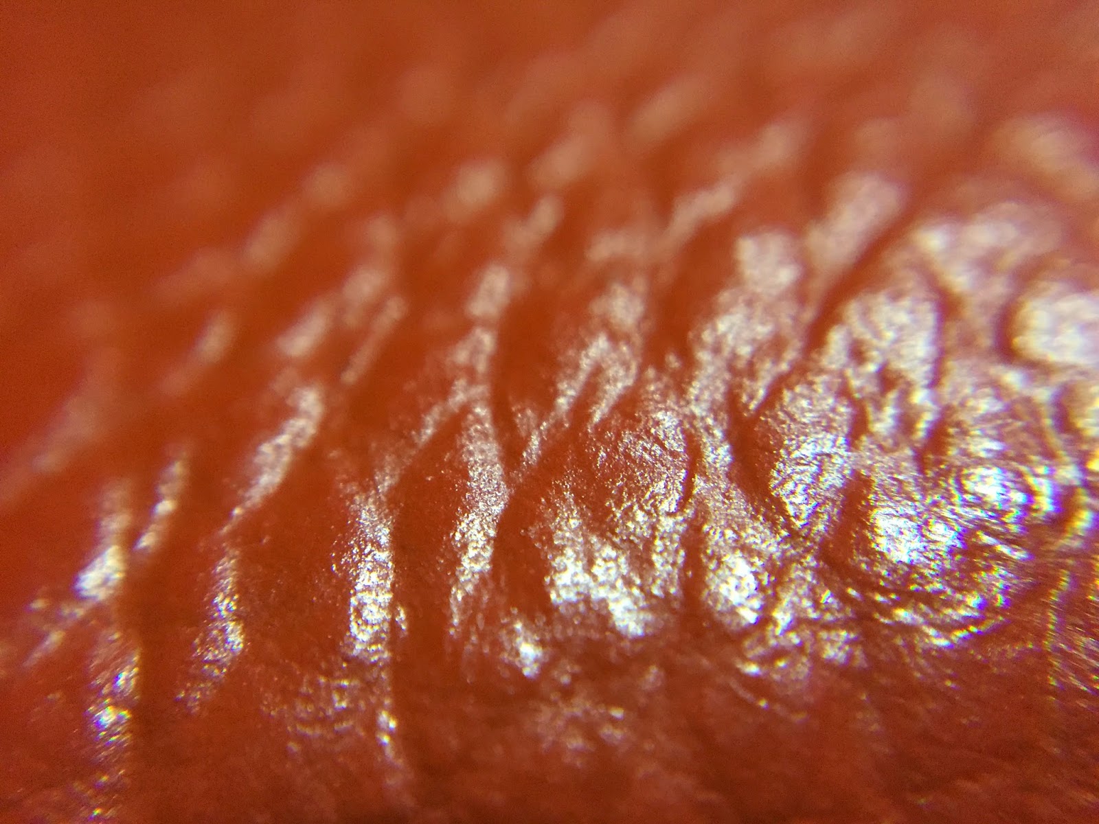
If you look closely at most surfaces, they won’t have smooth, clear, smooth specular highlights. Noise is everywhere, often "by design" e.g. with most formica countertops, and sometimes "naturally" even in plants, soft plastics, leather and skin notably.


Some surfaces have stronger spikes in certain directions and definitely “sparkle” visibly, even at scales we render today. Road asphalt is an easy and common example.


There are surfaces that have roughness at a frequency that is high enough to be represented always by a simple BRDF, but many are not. Some hard plastics (if not textured), glass, glazed ceramic, paper, some smooth paints.

Note: Eyes can be deceptive in this kind of investigation, for example Apple’s aluminum on a macbook or iphone looks “sparkly” in real life, but its surface roughness is probably too small to matter at the scales we render. 
This opens another can or worm that I won’t discuss, of what to do with materials that people “know” should behave in a given way, but that don’t really at the resolutions we can currently render at...

My Macbook Pro Retina

- Surfaces are anisotropic!

Anisotropy is much more frequent than one might suspect, especially for metals. We tend to think that only “brushed” finishes are really anisotropic, but when you start looking around you notice that many metals shows anisotropy, due to the methods used to shape them. 
Similar artifacts are sometimes found also in plastics (especially soft or laminated) or paints.


On the left: matte wall paint and a detail of its texture
On the right: the metal cylinder looks isotropic, but close up reveals some structure
It's also interesting to notice how the anisotropy itself can't be really captured by a single parameter, skewing the BRDF in a tangent space, but that there are many different distributions of anisotropic roughnesses.

- Surfaces aren’t uniform!

At a higher scale, if you have to bet how any surface looks at the resolutions we author specular roughness maps, it will always somewhat be non-uniform pixel to pixel.

You can imagine how if it’s true that many surfaces have roughness at frequencies that would require complex, multi-lobe BRDFs to render at our current resolutions, how it is even more likely that our BRDFs won’t ever have the exact same behaviour pixel to pixel.


Another way of thinking of the effects of using simpler BRDFs driven by uniform parameters is that we are losing resolution. We are using a surface representation that is probably reasonable at some larger scale, per pixel at a scale at which it doesn’t apply. So it’s somewhat similar to doing to right thing with wrong, “oversized” pixel footprints. In other words, over-blurring.

- Surfaces aren’t flat!

Flat surfaces aren’t really flat. Or at least it’s rare, if you observe a reflection over smooth surfaces as it “travels” along them, not to notice subtle distortions.

Have you ever noticed the way large glass windows for example reflect? Or ceramic tiles?


This effect is at a much lower frequency of course of the ones described above, but it’s still interesting. Certain things that have to be flat in practice are, to the degree we care about in rendering (mirrors for example), but most others are not.

- Conclusions

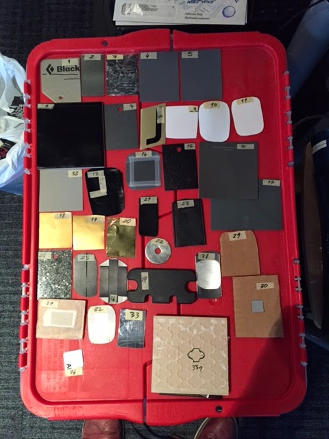
My current interest in observing surfaces has been sparkled by the fact I’m testing (and have always been interested) hardware solutions for BRDF scanning, thus I needed a number of surface samples to play with, ideally uniform, isotropic, well-behaved. And I found it was really hard to find such materials!


How much does this matter, perceptually, and when? I’m not yet sure. As it's tricky to understand what needs more complex BRDFs and what can be reasonably modeled with rigorous authoring of materials.


Textures from The Order 1886
Specular highlights are always "broken" via gloss noise,
even on fairly smooth surfaces


Some links:

17 December, 2013

Mental note: shadowmap-space filters

A thought I often had (and chances are many people did and will) about shadows is that some processing in shadowmap space could help for a variety of effects. This goes from blurring ideas (variance shadow maps and variants) to the idea of augmenting shadowmaps (e.g. with distance to-nearest-occluder information).

I've always discarded these ideas though (in the back of my mind) because my experience with current-gen told me that often (cascaded) shadowmaps are bandwidth-bound. To a degree that even some caching schemes (rendering every other frame, or tiling a huge virtual shadowmap) fail because the cost of re-blitting the cache in the shadowmap can exceed the cost of re-rendering.
So you really don't want to do per-texel processing on them, and it's better instead to work in screenspace, either by splatting shadows in a deferred buffer and blurring, or by doing expensive PCF only in penumbra areas and so on (i.e. with min/max shadowmap mipmaps to compute trivial-in shadow and trivial-out shadow cases and branch).

It seems though that lately caching schemes are becoming practical (probably they are already for some games on current-gen, by no mean my experience on the matter in Space Marines can be representative of all graphic loads).
In these cases it seems logical to evaluate the possibility of moving more and more processing in shadowmap space. 

Then again, a reminder that a great metaheuristic for graphics is to try to reframe the same problem in a different space (screen, light, UV, local, world... pixel/vertex/object...)

Just a thought.